How to Test a Circuit Breaker With a Multimeter in 6 Safe Steps
Learning how to test a circuit breaker with a multimeter takes two checks. First measure voltage at the breaker terminal while the panel is live. Then pull the breaker and check continuity. A healthy 120 volt breaker reads roughly 110 to 125 volts when switched on, and near zero ohms across its terminals. No voltage with the switch on usually means the breaker has failed.
Safety first. The main lugs inside your panel stay energized even when the main breaker is off. Never touch bus bars or lugs with bare hands. If you are unsure at any point, stop and call a licensed electrician.
This post contains affiliate links. We earn a commission when you purchase through our links at no extra cost to you. We only recommend products we’ve personally tested and use ourselves.
Why Testing a Breaker Matters
A circuit breaker is the cheapest safety device in your home and the one most people ignore. It carries current all day, heats up, cools down, and slowly wears out its internal contacts.
When it fails it rarely fails loudly. Most bad breakers simply stop passing power, or worse, refuse to trip when a fault appears downstream.
Testing takes ten minutes with a decent meter. That small effort tells you whether the problem sits in the breaker, the wiring, or the appliance itself.
It also saves you the cost of a service call for a fault you could have identified yourself in a single afternoon.
What You Need Before You Start
You do not need a lab bench for this job. Four items cover every test described below.
- A true RMS digital multimeter rated CAT III 600V or better for panel work.
- A non contact voltage tester to confirm dead circuits before touching anything.
- Insulated gloves and safety glasses for arc flash protection.
- An insulated screwdriver sized for your panel cover screws.
Category rating matters more than price here. A cheap meter with no CAT III rating can arc internally when it meets a fault current, and that failure happens inches from your face.
Check Multimeter Prices on Amazon
How to Test a Circuit Breaker With a Multimeter
Work through these six steps in order. Skipping the preparation steps is how most people get hurt.
Step 1: Kill the load and expose the panel
Switch off and unplug every appliance fed by the suspect circuit. Loosen the panel cover screws and lift the cover away carefully so it does not swing into the bus bars.
Leave the main breaker on for the voltage test. You need live power at the panel for that reading to mean anything.
Step 2: Confirm the panel is energized
Sweep your non contact tester across the incoming service conductors. It should alarm immediately.
If it stays silent, your problem is upstream at the meter or the utility drop, not at the breaker you suspect.
Step 3: Set the multimeter correctly
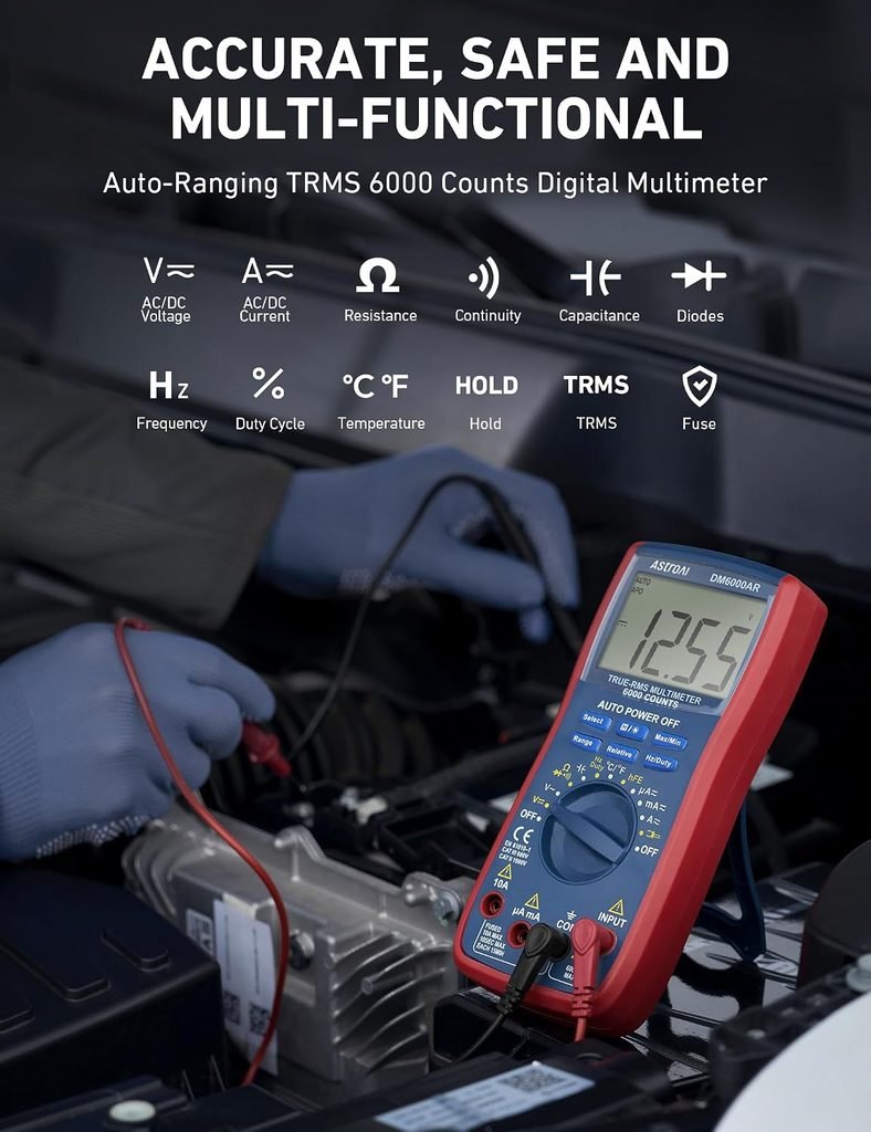
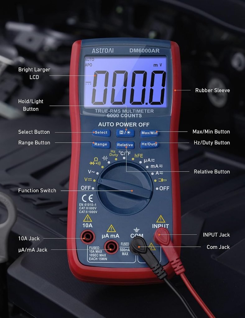
Turn the dial to AC voltage, shown as V with a wavy line above it. Select the 200 volt range on a manual meter, or let an auto ranging meter choose for you.
Plug the black lead into COM and the red lead into the socket marked V. Touch the probes together to confirm a stable zero reading.
Step 4: Measure voltage at the breaker terminal
Place the black probe on the neutral bar or the ground bar. Place the red probe on the screw terminal where the black circuit wire lands on the breaker.
Keep one hand behind your back while you work. That habit stops current crossing your chest if a probe slips.
A single pole breaker in the on position should read close to 120 volts. A double pole breaker should read about 240 volts across both terminals, and roughly 120 volts from each terminal to neutral.
Step 5: Interpret the voltage reading
Anything between 110 and 125 volts on a 120 volt circuit is normal. Homes on 230 volt systems should see roughly 220 to 240 volts.
Zero volts with the handle in the on position points squarely at a failed breaker. Reseat it once, retest, and if it still reads zero the breaker needs replacing.
A reading that flickers or drifts wildly suggests a loose terminal screw or a corroded bus clip rather than a dead breaker.
Step 6: Run a continuity test with the panel dead
Shut off the main breaker, verify with your non contact tester, then remove the suspect breaker from the panel.
Switch the meter to the continuity setting, marked with a sound wave symbol. Touch one probe to the load screw terminal and the other to the clip that grips the bus bar.
With the breaker handle on, expect a beep and a reading under one ohm. With the handle off, expect OL or infinity. A breaker that beeps in both positions is welded shut internally and is dangerous to reinstall.
Multimeter Readings Explained
| Reading | What It Means | Next Action |
|---|---|---|
| 110 to 125 volts AC | Breaker is passing power normally | Test the outlets and wiring downstream |
| 0 volts, handle on | Internal contacts have failed | Replace the breaker with an identical model |
| Under 100 volts | Poor connection or overloaded neutral | Torque the terminals and inspect the bus clip |
| Under 1 ohm, handle off | Contacts are welded closed | Discard the breaker immediately |
| OL, handle on | Open circuit inside the breaker | Replace the breaker |
Testing GFCI and AFCI Breakers
Modern panels often carry ground fault and arc fault breakers with a small test button on the face. A multimeter can confirm these breakers pass voltage, but it cannot verify their protective electronics.
Press the test button monthly. The handle should snap to the tripped position instantly, and the breaker should reset cleanly afterward.
If the button does nothing while your meter still reads 120 volts, the sensing circuit is dead even though power flows. Replace that breaker without delay because the protection you paid for no longer exists.
Common Mistakes That Ruin the Test
The most frequent error is testing a breaker that was never the problem. Always check the outlet or fixture first, because loose backstab connections cause far more dead circuits than failed breakers.
The second mistake is leaving the meter on the resistance setting while probing a live panel. That combination can destroy the meter and create a flash hazard.
Finally, never judge a breaker by its handle position alone. A tripped breaker often rests in a middle position that looks like on but carries no power at all.
When to Replace and When to Call an Electrician
Swapping a standard single pole breaker is within reach of a careful homeowner in most regions. The job takes fifteen minutes and the part usually costs less than a restaurant meal.
Match the replacement exactly. Brand, amperage, and panel series must all agree, because breakers from one manufacturer rarely seat safely in another maker’s bus.
Call a professional if you find scorch marks, melted insulation, or a bus bar that looks pitted. Those signs point to heat damage that a new breaker will not solve.
You should also step back if your panel is a discontinued line with known safety recalls. Several older brands developed reputations for breakers that failed to trip under load, and those panels deserve a full inspection rather than a single part swap.
One more rule worth keeping. If the same breaker trips again within days of replacement, stop replacing parts and start tracing the circuit, because a repeat trip is the breaker doing its job correctly.
Frequently Asked Questions
Can I test a circuit breaker without removing it from the panel?
Yes. The voltage test in Step 4 is performed with the breaker installed and the panel live. Only the continuity test requires removal.
What multimeter setting do I use to test a circuit breaker?
Use AC voltage for live panel testing, usually the 200 volt range. Use the continuity or ohms setting for bench testing a removed breaker.
Why does my breaker show voltage but the outlet stays dead?
The breaker is fine and the fault sits downstream. Look for a broken neutral, a failed outlet, or a loose wire inside a junction box on that run.
How often do circuit breakers actually fail?
Failures are uncommon in the first decade, but breakers that trip frequently or sit in hot panels wear far faster. Manufacturers generally recommend replacement after thirty to forty years.
Is a clamp meter better than a multimeter for this job?
A clamp meter measures current draw without breaking the circuit, which helps diagnose overloads. For voltage and continuity checks a standard multimeter is all you need.
Ready to test your own panel safely?
A properly rated meter is the difference between a confident diagnosis and a guess.See Top Rated Multimeters on Amazon
Keep going with our side by side tool comparison or build a kit list with the project tool checklist.
Also Read On:
Why OSHA Compliant Fall Protection Harnesses Are Not Optional
Best NRR Rated Ear Protection for Loud Power Tools in 2026
How to Use an Angle Grinder for Carving: A Comprehensive Guide